
Typical features
- Three-phase liquid-filled construction.
- Natural and forced cooling ratings specified for the required duty.
- Power transformer designs for utility and industrial systems.
Power transformers
Liquid-filled power transformers for utility substations, industrial facilities and large-load projects. Reference capacities include 25, 45, 50 and 60 MVA.
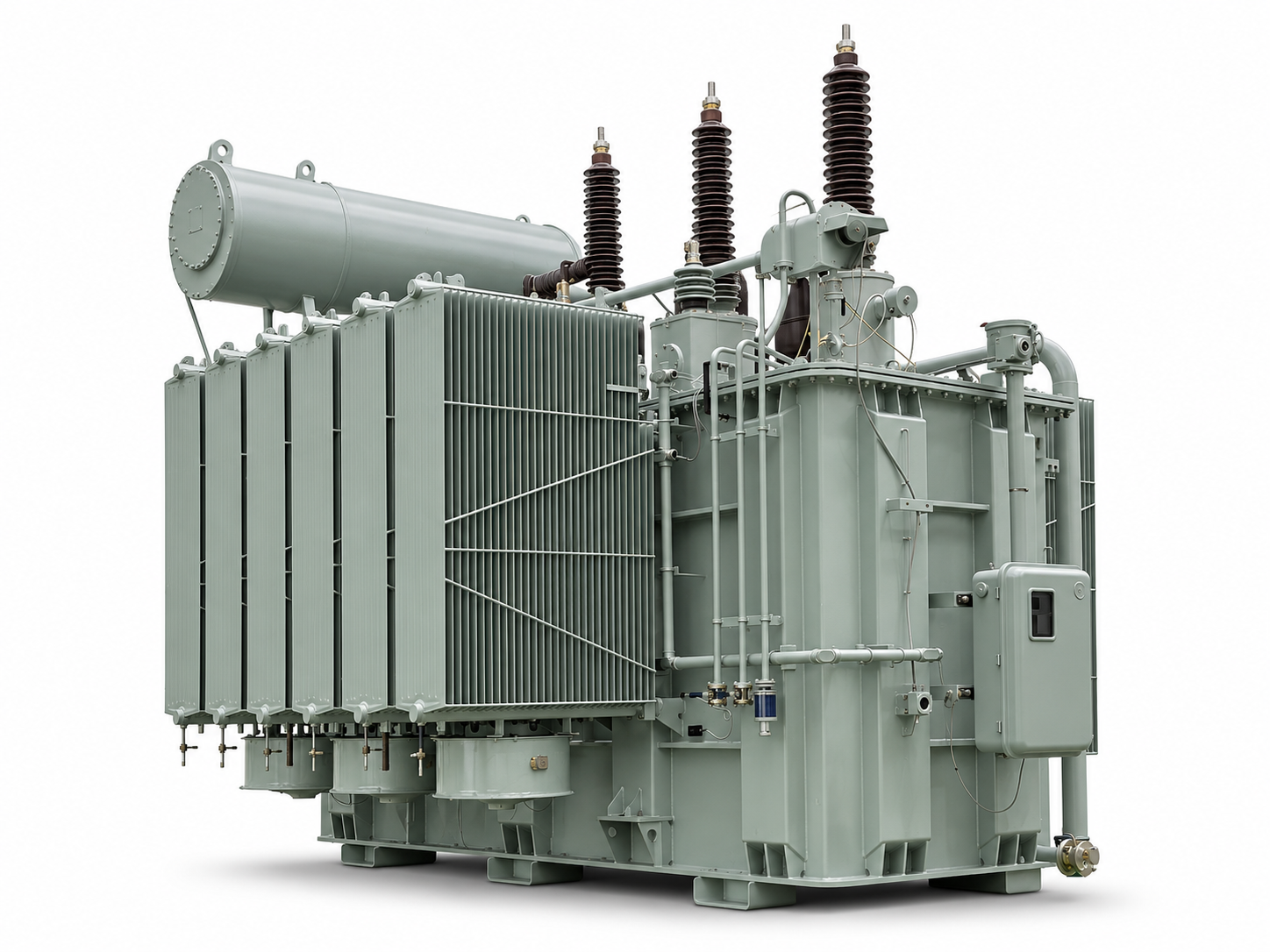
138 kV / 34.5 kV power transformer reference design.
| Parameter | Reference value |
|---|---|
| Rated capacity / cooling | 45 MVA ONAN / 60 MVA ONAF |
| Primary / secondary voltage | 138 kV Delta / 34.5Y/19.92 kV |
| Phase / frequency | Three-phase / 60 Hz |
| Winding connection / material | Dyn1 / copper-copper |
| Insulating fluid | Mineral oil |
| Average winding temperature rise | 65 K |
| BIL, HV / LV | 650 / 200 kV |
| Neutral BIL design basis | 150 kV |
| Impedance | 10% at 45 MVA, rated tap; IEEE tolerance |
| HV voltage regulation | Vacuum-type OLTC; ±10%, 33 positions |
| Cooling arrangement | Two fan stages; no oil pumps |
| Protection | Buchholz relay, pressure-relief device, sudden-pressure relay |
| Monitoring | Oil and winding temperature, oil level, online gas and moisture |
| Controls / communication | Outdoor NEMA 4X control cabinet / Modbus TCP |
| Altitude / ambient design basis | Below 1,000 m / -25°C to +40°C |
| Design / test standards | IEEE C57.12.00 / C57.12.10 / C57.12.90 / C57.131 |
69 kV / 24.9 kV power transformer reference design.
| Parameter | Reference value |
|---|---|
| Rated capacity / cooling | 25 MVA ONAN / 31.25 MVA ONAF |
| Primary / secondary voltage | 69 / 24.9 kV |
| Phase / frequency | Three-phase / 60 Hz |
| Winding connection / material | Dyn1 / copper |
| Insulating fluid | Mineral oil |
| Winding / top-oil rise | 65 / 65 K |
| Hot-spot rise | 80 K |
| BIL, HV / LV and neutral | 350 / 150 kV |
| Power-frequency withstand, HV / LV | 140 / 50 kV |
| Impedance | 8% at 25 MVA, 85°C; standard tolerance |
| No-load loss | 30 kW |
| Load loss | 80 kW at 25 MVA, 85°C |
| HV / LV tap adjustment | HV de-energized ±2 × 2.5%; LV OLTC ±16 × 0.625% |
| Approximate total / oil weight | 79,800 / 21,300 kg |
| Main-body transport, L × W × H | Approx. 6,200 × 3,100 × 3,100 mm; nitrogen-filled |
| Main-body transport weight | Approx. 51,050 kg |
| Design / test basis | IEC 60076 / IEEE; routine factory tests |
Reference configurations are illustrative. Final specifications, certification and drawings are confirmed for your project.
Send your MVA ratings, primary and secondary voltages, quantity, delivery location and required date.